
Analog Instrument
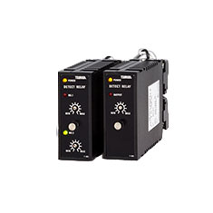
Detect Relay
■ Suitable for overload protection and abnormal detection of motor.
■ Max. 20 signals can be obtained for just 1 signal input.
■ Two types of setting are available : Digital type and screw type
Note: Auxiliary unit 2422 is used together with the main unit 2411 or 2421. It can not be connected to some of AC input models. .
| Product Name | 1ch Main Unit | 2ch Main Unit | 2ch Auxiliary Alarm Output Unit |
|---|---|---|---|
| Model Configuration | 2411 | 2421 | 2422 |
| Code | 2411 | 2421 | 2422 |
|---|---|---|---|
| D | Digital switch setting | ||
| S | Screw driver setting | ||
| Code | 2411 | 2421 | 2422 |
|---|---|---|---|
| 1 | Digital switch setting | HL Setting, relay contact output | |
| 2 | L Setting, relay contact output | HH Setting, relay contact output | |
| 3 | H Setting, open collector output | LL Setting, relay contact output | |
| 4 | L Setting, open collector output | HL Setting, open collector output | |
| 5 | - | HH Setting, open collector output | |
| 6 | - | HH Setting, open collector output | |
| Code | 2411 | 2421 | 2422 | |
|---|---|---|---|---|
| -- | DC Signal | Note: 2422 is the auxiliary unit, so it accepts no input signal and no specification of ③ is required. |
||
| 02 | DC 0 to 100 mV | |||
| 03 | DC 0 to 1 V | |||
| 04 | DC 0 to 5 V | |||
| 05 | DC 0 to 10 V | |||
| 09 | DC 1 to 5 V | |||
| 00 | Other DC voltage input (60 mV≦00 ≦300 V) | |||
| 22 | DC 0 to 100 μA | |||
| 23 | DC 0 to 1 mA | |||
| 24 | DC 0 to 5 mA | |||
| 25 | DC 0 to 10 mA | |||
| 29 | DC 4 to 20 mA | |||
| 20 | Other DC current input (100 μA≦20 ≦1 A) | |||
| - | AC signal (Effective value rectification type) | |||
| 44 | AC 0 to 150 V rms | |||
| 46 | AC 0 to 300 V rms | |||
| 40 | (100 mV≦40≦300 V) | |||
| 53 | AC 0 to 1 A rms | |||
| 54 | AC 0 to 5 A rms | |||
| 50 | (100 mA≦50≦5 A) | |||
| - | AC signal (Rectification type) |
|||
| 73 | AC 0 to 1 A | ※Half wave peak detection system | ||
| 74 | AC 0 to 5 A | |||
| 70 | (100 mA≦70 ≦5 A) | |||
④Hysteresis
| Code | Specifications |
|---|---|
| H0 | Less than 0.5 % , standard |
| H1 | approx. 1 % |
| H2 | approx. 2 % |
| H3 | approx. 3 % |
| H4 | approx. 4 % |
| H5 | approx. 5 % |
| Code | Specifications |
|---|---|
| T0 | No delay, standard |
| T1 | approx. 1 s |
| T2 | approx. 2 s |
| T3 | approx. 3 s |
| T4 | approx. 4 s |
| T5 | approx. 5 s |
| Code | Specifications |
|---|---|
| A | AC 85 to 250 V 50/60 Hz |
| 9 | DC 20 to 30 V |
| C | DC 90 to 170 V |
Note: Specifications of ④Hysteresis, ⑤Power
On Delay and ⑥Power Supply Voltage are common for 2411, 2421 and 2422.
Specifications
| Specification / Model | 2411D/2411S | 2421D/2421S | 2422D/2422S | ||
|---|---|---|---|---|---|
| D : Digital switch setting S : Screw driver setting |
 |
 |
 |
||
| Dimension (W x H x D mm) excl .Base socket | 28.5 × 72 × 115 | ||||
| Input | DC current / voltage(Moving coil) | ● | ● | - | |
| Process | ● | ● | - | ||
| AC current / voltage | ● | - | - | ||
| Output | Nos. of Alarm | 1point | ● | - | - |
| 2points | - | ● | ● | ||
| Accuracy | Setting (exclude pot.setting) |
within ± 0.5 % of Max.value | |||
| Repeatability | within ± 0.1 % | ||||
| Output | Relay | ● | ● | ● | |
| Open collector | ○ | ○ | ○ | ||
| Setting style | Thumb | ● | ● | ● | |
| Potentiometer | ● | ● | ● | ||
| Alarm type (H/L) | H or L fixed | ● | ● | ● | |
| Rating | Relay | 250 V, 0.5 A a.c., 30 V, 2 A d.c. | |||
| Open collector | 50 V, 100 mA d.c. | ||||
| Response |
|
||||
| Function | Hysteresis | ○ | ○ | ○ |
| Output delay | ○ | ○ | ○ | |
| Power on delay | ● | ● | ● | |
| Operating temperature | 0-50°C | |||
| Operating humidity | 30 - 90%RH (no condensation) | |||
| AC power supply | 85 – 264 V a.c. | |||
| DC power supply | 20 – 30 V d.c., 90 – 170 V d.c. | |||
| Weight | approx. 170 g | |||
![]() Operation Manual
Operation Manual