
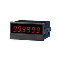
Integrating Digital Panel meter (Pulse input)
MODEL:461B
■ Compact 96 x 48 DIN Size, with the front cover
■ Switch display and output of flow rate and totalizer
■ Programmable from the front panel
■ Pulse input 461B
Model Designation
| 461B | |
|||||
1 |
2 |
3 |
4 |
5 |
6 |
1. Power supply voltage
| Code | Power source voltage |
A |
AC90~264V 50/60Hz |
9 |
DC24V±10% |
2. Power source for sensor
| Code | output voltage | output current |
Blank |
- |
|
3 |
DC12V±5% | 150mA |
5 |
DC24V±5% | 100mA |
3. Analog output
| Code | Analog output | Output impedance | Tolerable Load resistive | |
Blank |
- |
|||
03 |
Instantaneos value output |
DC0~1V | Approx.
0.1MΩ |
200Ω or more |
04 |
DC0~5V | 1kΩ or more | ||
05 |
DC0~10V | 2kΩ or more | ||
09 |
DC1~5V | 1kΩ or more | ||
29 |
DC4~20mA | 5MΩ or
more |
0~600Ω | |
03T |
Totalized value output |
DC0~1V | Approx.
0.1MΩ |
200Ω or more |
04T |
DC0~5V | 1kΩ or more | ||
05T |
DC0~10V | 2kΩ or more | ||
09T |
DC1~5V | 1kΩ or more | ||
29T |
DC4~20mA | 5MΩ or
more |
0~600Ω | |
4. BCD output,RS-232C,RS-485
| Code | Data output |
Blank
|
- |
BP
|
BCD output (TTL level positive logic) |
BN
|
BCD output (TTL level negative logic) |
DP
|
BCD output (transistor output,source type) |
DN |
BCD output(transistor output,sink type) |
E0 |
RS-232C |
E1 |
RS-485 |
5. Preset output
| Code | preset output |
Blank
|
No preset output |
R
|
Instaneous:
H・L Totalizing:With Change-over of H・HH or 2batch steps setting |
6. Display color
| Code | Color |
Blank
|
Red LED |
G
|
Green LED |
Basic Specifications
| Flow rate
measurement |
|
| Flow indication | 0~999999: Red or Green
LED, Character 15mm High, with
zero-suppress function. Programmable Decimal point from the front panel Over: flashes "000000" |
| Display cycle | Selectable from the front key. 3.3 time/sec, 1 time/sec., 0.2 time/sec. |
| Pulse Conversion | Selectable from the front key, from 1×10⁻⁶ to 1000 |
| Unit | Selectable from the front key, Hour, minute, second |
| Accuracy | ±(0.05%+1 digit) |
| Flow totalize
measurement |
|
| Flow indication | 0~999999: Red or Green
LED, Character 15mm High, with
zero-suppress function. Programmable decimal point from the front panel. |
| Over-range indication | Flashes and counts from "0" when exceeding, with enable/disable function. |
| Integration constant | from 1×10⁻⁹ to 1, programmable from the front key. |
| Primary integrated value | from 0 to 999999, programmable from the front key |
| Common
Specifications |
|
| Input signal | Input 1: Non-voltage
contact or NPN open collector Input 2: Voltage pulse, “H”=4.5~30V “L”=0~2.0V Selectable Input 1 or 2 from the front key Note for wrong count by chattering when using relay contact. |
| Input frequency | Selectable from the front key, HF range (5Hz to 1kHz) or LF range (0.0166Hz to 100Hz) |
| Cut off | 0 to 10%: Programmable from the front key. |
| Latch / Pose input | Latch: hold display of
instantaneous and integrating flow rate,
and data output. Accumulated integrated
count and P.O. output will be insulated. Pose: hold display of instantaneous and integrating flow rate, and data output. Accumulated integrated count will be stopped. Integrating synchronizing pulse output (P.O.): Input and isolation output. Output signal is NPN open collector output. |
| Reset | reset totalized value and primary setting value |
| Blackout | All programmed settings are stored in EEPROM for a minimum of ten years if power is lost. It does not count when shutting or losing the power. |
| Noise rejection | 1000V against the power line noises |
| Withstanding Voltage | Input terminals - Case :
AC2100V each for 1 min. Power supply terminals - Case : AC1500V each for 1 min. Power supply terminals - Input and Output terminals : AC1500V each for 1min. Input terminals - Output terminals : AC500V each for 1 min. |
| Insulation Resistance | DC500V 100MΩor more. |
| Power Supply | AC 90 to 264V (50/60Hz), DC24V±10% |
| Power Consumption | Approx. 16VA at AC power supply, 300mA at DC power supply |
| Operating Temperature | 0 to 50℃ |
| Storage Temperature | -20 to 70℃ |
| Weight | Approx. 500g |
![]() Operation Manual
Operation Manual